Static AC Circuit Breaker
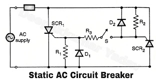
Circuit diagram of Static AC Circuit Breaker :
- The circuit diagram of the static AC circuit breaker is e shown in Figure SCR1 is turned on in the positive half cycle whereas SCR2 is turned on in the negative hat cycle of the ac supply, as soon as we close switch S.
Operation of Static AC Circuit Breaker :
- During the positive half cycle of the ac supply, SCR2 receives the gate current through R2, S and R3 and turns on. This SCR turns off due to natural commutation at the end of the positive half cycle. The positive half cycle thus appears across the load.
- During the negative half cycle, SCR2 receives gate current through R1, R3 and S and turns on. At the end of the negative half cycle, this SCR is turned off due to natural commutation. The negative half cycle thus appears across the load.
- When the load current is to be stopped, the switch "S" is open circuited. This will not allow the gate current of both the SCRs to flow and will not allow them to tum on (Note that switch S happens to be in series with gates of both the SCRs).
- However when S is open circuited, the conducting SCR will continue to conduct upto the end of the current half cycle of the ac supply. That means S1 continues to conduct till the end of the current positive half cycle while S2 continues to conduct upto the end of current negative half cycle. This corresponds to the maximum time delay in breaking the circuit.
- So the maximum time delay for breaking the circuits ope half cycle i.e. 10 mS.
